tdt.DSPCircuit – Wrapper for RPvds circuit objects
Wrapper around a RPvds circuit
>>> from tdt import DSPCircuit
>>> circuit = DSPCircuit('acquire_neurophysiology.rcx', 'RZ5')
Parameters
- circuit_name : path (required)
- Absolute or relative path pointing to the file containing the circuit microcde (e.g. the *.rcx file).
- device_name : str (required)
- Target device to load the microcode to (the name will be in the format RP2, RX6, RX8, RZ5, RZ6, etc.).
- device_id : int (optional, default=1)
- Specifies which of the two devices to load the microcode to. Required only if you have more than one of the same device (e.g. two RP2 processors). Use TDT’s zBUSmon utility to look up the correct device ID.
- load : boolean (optional, default=True)
- Load the circuit to the device when class is initialized? True by default. Typically you would set it to False when you want to inspect the DSP microcode without actually running it.
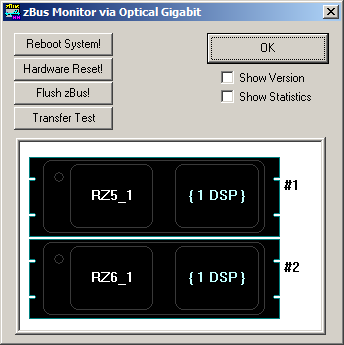
If you’re not sure what to enter for device_name and device_id, use TDT’s zBUSmon utility to look up the correct information. As shown in the screenshot below, two devices installed in the system are the RZ5_1 and RZ6_1. The device names are RZ5 and RZ6, respectively, while the device ID is 1 for both. If zBUSmon reports that you have a RZ5_1 and RZ5_2, then both device names would be RZ5 while the device ID would be 1 and 2, respectively.
Available public attributes
- fs : float
- Sampling frequency of the circuit
- tags : dictionary
- Keys are the tag names (i.e. variables) present in the DSP microcode. Values are a tuple of tag size and tag type. Note that tdt.constants defines the available tag types. For simple types (e.g. integer, float and boolean), the tag size will always be 1. For buffer types, the size will indicate the number of 32 bit words in the buffer.
- scalar_tags : list
- List of tag names present in the DSP microcode that have a tag size of 1 (i.e. a scalar value such as an integer, float or boolean).
- vector_tags : list
- List of tag tag names (i.e. variables) present in the DSP microcode that have a tag size >= 1 (i.e. buffer or coefficient tag).
- name : str
- Name of circuit currently loaded
- path : str
- Full path of circuit on disk
Brief example of the public attributes available for the example circuit, record_microphone.rcx shown in the introduction:
>>> print circuit.fs
97656.25
>>> print circuit.scalar_tags
['mic_i', 'speaker_i', 'play_dur_n', 'record_del_n',
 'record_dur_n', 'recording', 'playing', 'running']
>>> print circuit.vector_tags
['speaker', 'mic']
>>> print circuit.name
example_circuit.rcx
>>> print circuit.tags
{'mic': (100000, 68),
 'mic_i': (1, 73),
 'play_dur_n': (1, 73),
 'playing': (1, 76),
 'record_del_n': (1, 73),
 'record_dur_n': (1, 73),
 'recording': (1, 76),
 'running': (1, 76),
 'speaker': (100000, 68),
 'speaker_i': (1, 73)}
Error handling
Attempting to get/set the value of a nonexistent tag in the circuit will raise a DSPError:
>>> circuit.get_tag('nonexistent_tag')
DSPError: 'nonexistent_tag' not found in circuit
Note
If you have a tag linked to a static datatype the DSPCircuit class will raise an exception. Since the ActiveX driver cannot read from (or write to) this tag, this typically indicates a design error in the RPvds circuit.
Suggested code conventions
Sharing code across circuits
The current version of TDT’s real-time processor visual design studio (RPvds) does not facilitate code reuse. The macro system is undocumented and clearly not meant for general use. For example, a macro embedded into a circut has the absolute path to the macro hard-coded. This makes it extremely difficult to place circuits using macros under revision control and maintain multiple branches on the same computer. The copy of the circuit in each branch will insist on loading the macro stored in the directory of the original branch where the commit was made, not the location of the macro in the new branch. Furthermore, if you decide to move your code to a new folder, you must manually update the reference to the macros in each circuit you use (even if the relative path between the macro and circuit remains unchanged).
Instead, create a page in your circuit file that contains only the shared code that you would like each circuit to use. Whenever you update the code on this page, it’s easy to cut and paste the modified code to the other circuits that also use it. Just be sure to keep the same naming conventions for whatever tags and hops you use in the common portion of the code.
Tag naming
Use right-pointing tags to indicate that they are meant to be written and left-pointing tags to indicate they are meant to be read. Although a tag can be used for both purposes, it makes it much easier for a new programmer to ascertain the purpose of the tag. Is it meant to be a setting that can be modified via the software, or does it hold data that is meant for the software?
If the output of the tag reflects an epoch boundary, use the ‘/’ suffix to indicate the start and ‘’ to indicate the end. If it is simply a point in time (i.e. a timestamp), use the ‘|’ suffix.
If the tag requires a certain unit (e.g. msec or number of samples), be sure to indicate the unit in the tag name using the appropriate suffix. For example, tags requiring a value in msec should have the suffix ‘_ms’ and tags requiring the number of samples should have the suffix ‘_n’.
Hop naming
Use the ‘_start’ and ‘_end’ suffix to indicate the hop reflects a logical value that is true for only one cycle of the sample clock (i.e. the output of an EdgeDetect component). Use the ‘_TTL’ or ‘_window’ suffix to indicate that the hop reflects a logical value that is true for some duration of time.
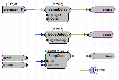
zBUS trigger A
In many cases it’s a good idea to put most of the circuit under control of zBUS trigger A using the following circuit construct.